IMUnipulator
Students in Northwestern University’s CE346 Microprocessor System Design course complete a final project, with the goal of designing a microcontroller device to achieve some creative task. For the project, we programmed a micro:bit v2 (based on the Nordic nRF52833 SoC) in C.
Our team, IMUnipulator, decided to collaborate with another group, EMGripper, to create the IMUGripulator! This device was a 2-DoF robotic arm with joints controlled by a 9-DoF inertial measurement unit (IMU) attached to someone’s hand (IMUnipulator’s portion of the project). The end-effector of the arm was a gripper controlled by an EMG sensor and force-sensitive resistor (EMGripper’s portion of the project).
Here’s a demo of the full device:
Table of Contents
Design
The core of the IMUnipulator consists of two servos for actuating the arm and an IMU attached to the arm of the user with a bracelet. The micro:bit microcontroller gets signals from the IMU which it uses to command positions of the servos.
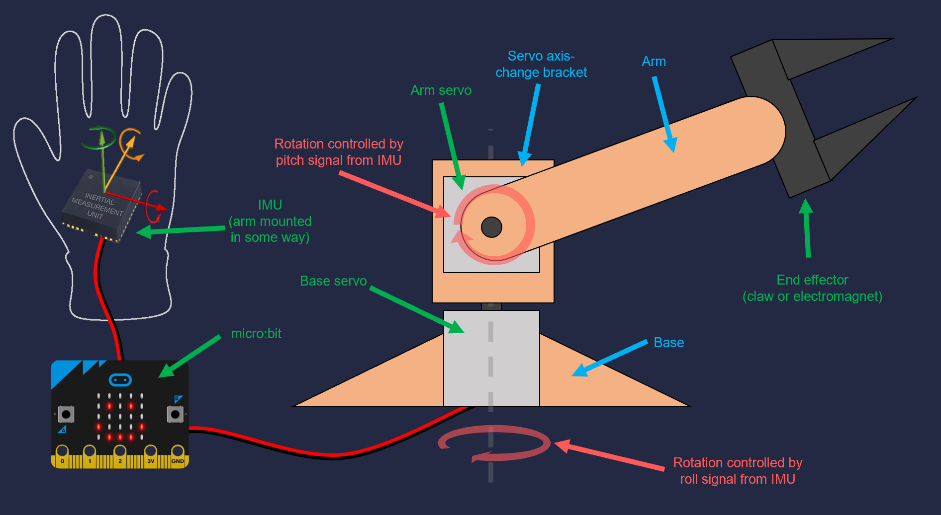
A basic diagram of the IMUnipulator device.
The micro:bit collects roll and pitch data via I2C from the IMU’s accelerometer and converts the data into degrees of tilt in each axis. If either axis indicates a tilt that is higher than a certain threshold, the corresponding servo will be commanded to move.
The roll axis controls the lower joint of the arm, called the “base” joint. The pitch axis controls the upper joint of the arm, called the “arm” joint. To simplify user experience, only one axis can move at a time, and the arm joint is prioritized over the base joint.
Finally, the arm can be returned to its default “home” position via a touch of an external capacitive touch sensor.
Expand for more technical details on the control logic.
The servos are controlled via PWM duty cycles, each one indicating a different position to which the servo should move. The micro:bit sends data over I2C to set the value of that duty cycle to the PCA9685, which in turn produces a PWM signal with that duty cycle. Each servo has a mechanical limit of 180 degrees of rotation, though the arm joint is limited in software to less than that so it won’t collide with the ground.
While an IMU axis remains tilted beyond its threshold, the servo commanded position is incremented/decremented at a certain rate. This rate can be controlled by the “sensitivity” level of the arm, which is adjusted via the micro:bit’s built-in capacitive touch sensor and indicated by the built-in LED matrix.
Drivers
We had to write several drivers in order to interface with the various devices used.
I2C
A general use driver to communicate with a device on one of the micro:bit’s I2C buses.
IMU
A driver that uses the I2C driver to communicate with the Adafruit TDK InvenSense ICM-20948 9-DoF IMU’s accelerometer and convert the received acceleration data into tilt angles.
Servos
A driver that uses the I2C driver to communicate with the Adafruit PCA9685 I2C 16-Channel 12-bit PWM Driver. This external board takes commanded duty cycles over I2C and translates them to PWM signals, which are then sent out to the MG996R and DS3218 servos used in the robot joints. Each duty cycle corresponds to a certain rotational position for the servo, from 0 to 180 degrees. Interestingly, although this duty cycle to servo angle relationship was supposed to be linear, using a simple linear equation to calculate duty cycle from desired angle didn’t actually work very well. Instead, we had to take several data points for different desired angles and commanded duty cycle relationships, store them in arrays, and linearly interpolate between them to get accurate servo positions.
Testing out the servo driver by moving the two servos in unison through their range of motion.
Capacitive Touch
A driver that determines if the micro:bit’s built-in “capacitive touch sensor” (really just a pin connected to the micro:bit logo) has been touched. External SparkFun AT42QT1011 Capacitive Touch Breakouts were also used, but these just provided a digital signal to GPIO pins and did not require this special driver.
LED Matrix
A driver to control the micro:bit’s built-in LED matrix, which was used to indicate the arm’s current sensitivity level.
Mechanical Hardware
Although the focus of the project was the electrical and software design, the team also did some mechanical design, primarily for 3D printed components. All of these components were printed out of PETG on a Prusa i3 MK2.
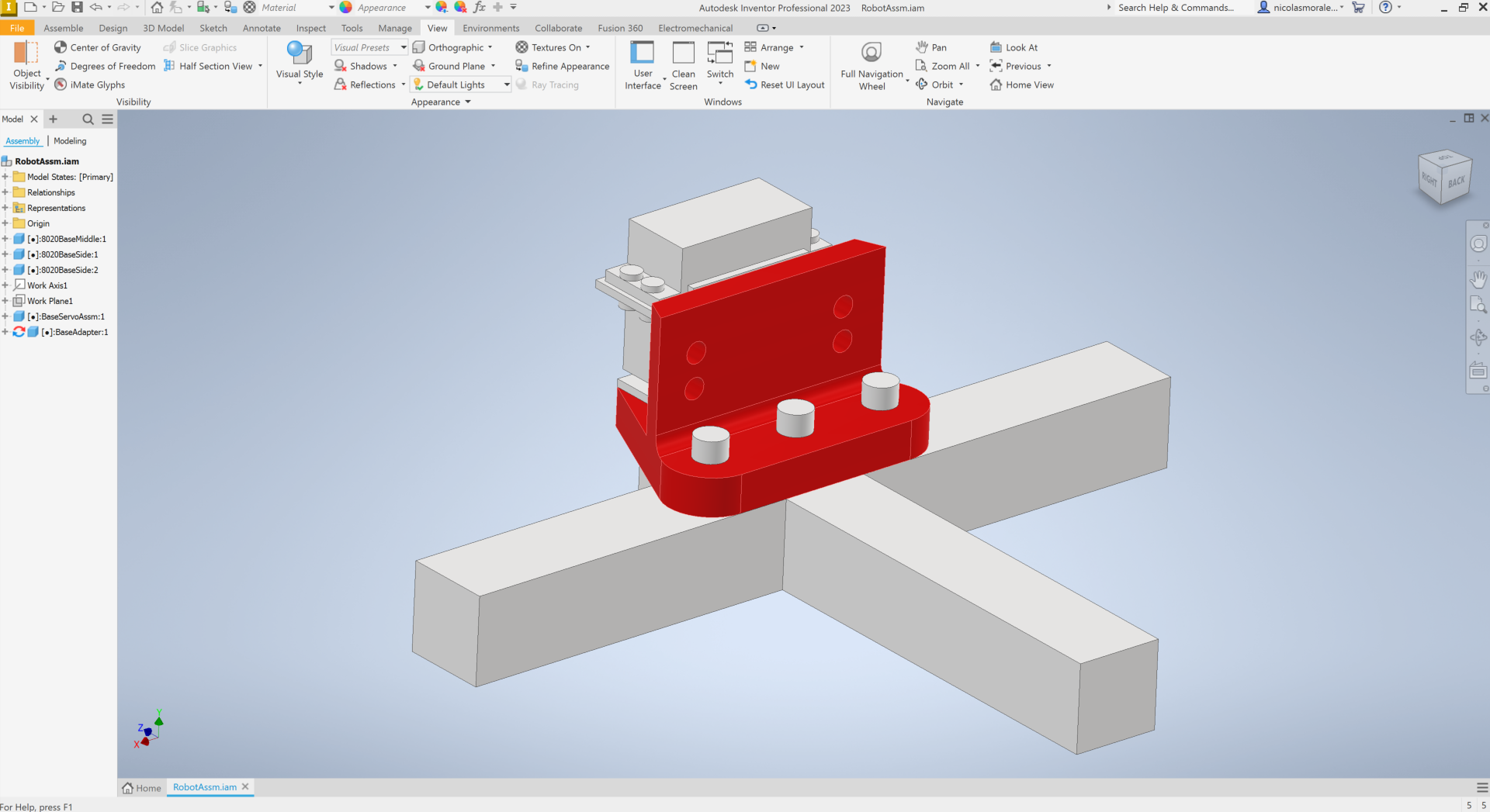
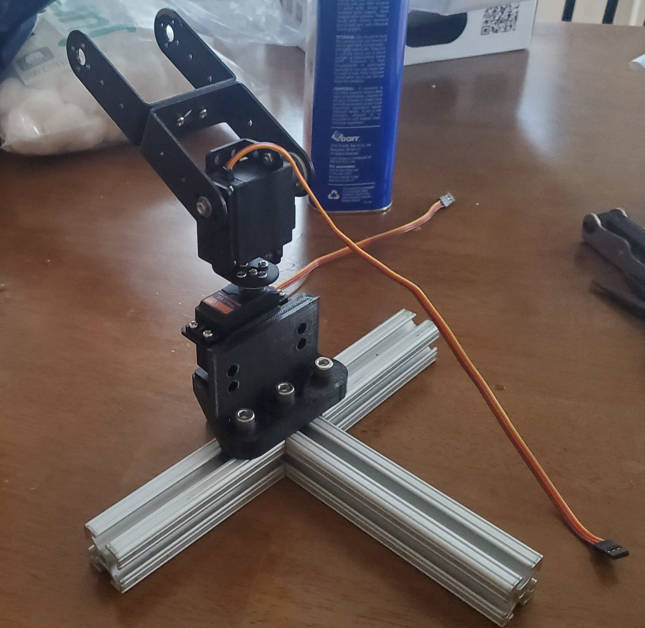
Base
Some of the arm components were already provided by a small robot arm kit that one of the EMGripper team had on hand. But in order to use these in the configuration we wanted, we had to design a simple base. It was constructed out of 1-inch 80-20 bars to provide solid weighted base, and a custom adapter was designed to mate the arm components with the 80-20.
End-Effector Options
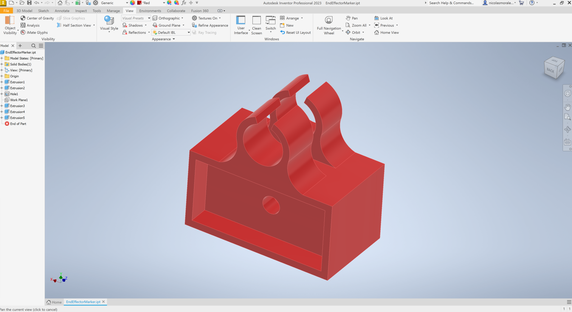
The IMUnipulator was designed to have several different end-effector options that can be quickly switched out.
-
Marker Holder - this end effector held a whiteboard marker so you could draw any blocky pictures you want - since the arm only moves in one axis at a time.
-
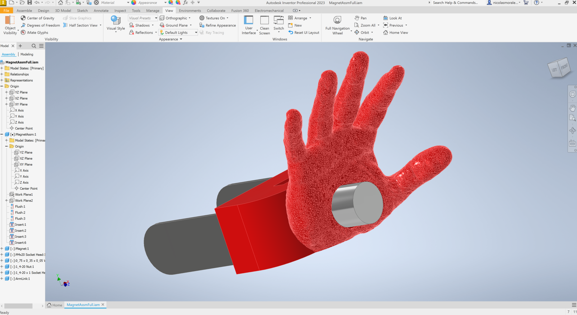
Electromagnet Hand - use The Force to pick up objects! Well, metal ones at least, since the “force” is electromagnetism.
- EMGripper - by far our favorite end-effector. This team’s project uses an EMG sensor to detect muscle contractions in the user’s arm and close a gripper using a servo. A force sensitive resistor on the gripper prongs prevents the gripper from continuing to close once it reaches a force limit.
Team
The IMUnipulator team worked together on the software, electrical, and mechanical design of the arm. It consisted of:
- Felipe Jannarone
- Nick Morales
- Hang-Yin
The EMGripper team produced the EMGripper end effector shown in the videos. It Consisted of:
- David Dorf
- Katie Hughes
- James Oubre
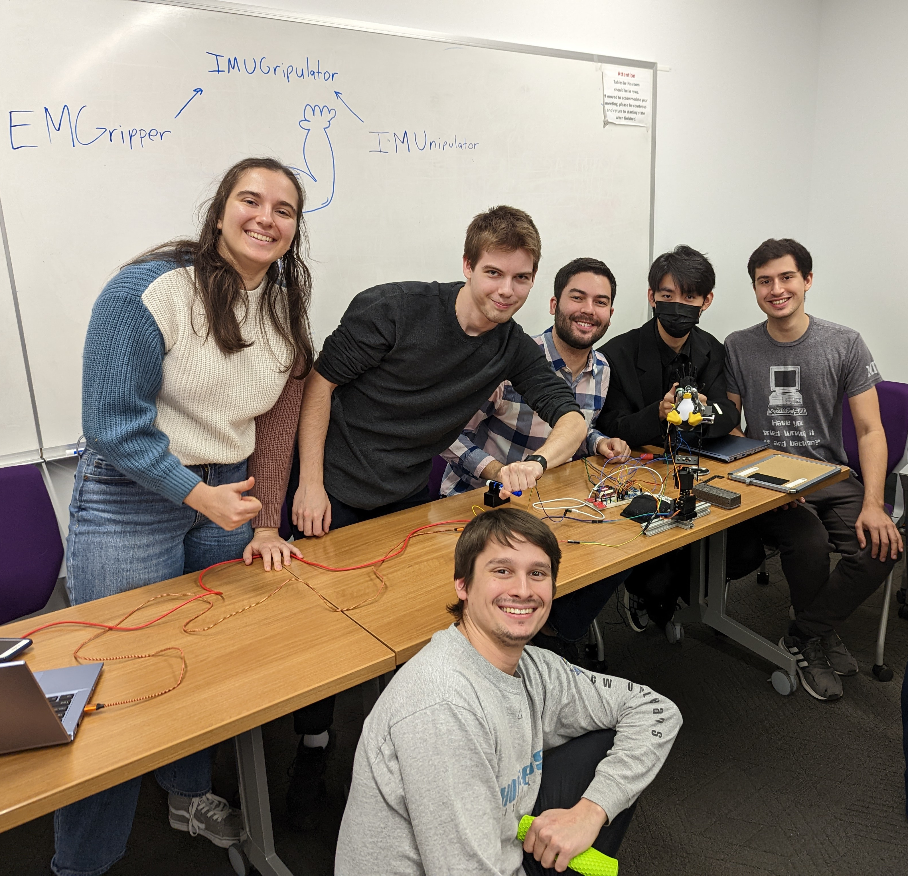
The full IMUGripulator team!