Attack of the Franka
For our final project in Northwestern University’s ME495 Embedded Systems in Robotics class, my team decided to program a 7-DoF Franka Emika Panda robotic arm to autonomously wield a lightsaber to help the Republic fight the Separatists.
The robot (which we dubbed “Franakin Skywalker”) must draw the lightsaber from a sheath and swing it to knock over members of the Separatist Army, represented by red blocks placed upright on a work area table. Franakin will also need to avoid its ally blue blocks, representing members of the Republic. The setup of the allies and enemies in the work area is configured arbitrarily by a human.
The Python-based system uses an Intel RealSense D435i and OpenCV to detect and differentiate the blocks and controls the robot arm via MoveIt in ROS 2.
Table of Contents
Computer Vision
The CV system consists of a few ROS 2 packages working in concert and tied together via a Python camera_processor node.
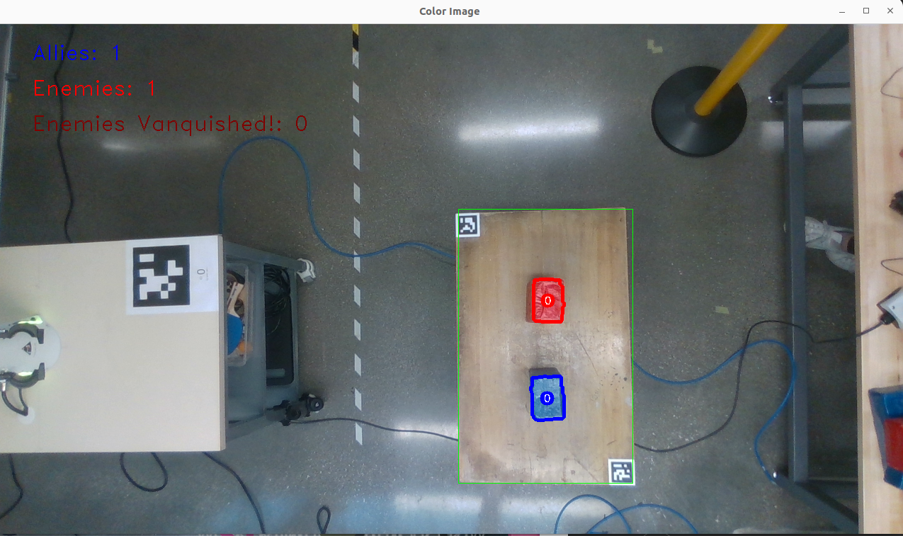
A single ally and a single enemy, as seen from the RealSense’s camera feed.
Color image data and depth data are published from the RealSense camera. An AprilTag detection package detects three AprilTags from this camera data, which help determine the relative location of the robot to the camera and the bounds of the work area.
Expand for more technical details on the AprilTag system.
First, the ROS 2 wrapper for Intel RealSense devices is used to connect to the RealSense and publish color image data and depth data that is aligned with the color image camera reference frame.
Next, the April Robotics AprilTag library is used along with Christian Rauch’s ROS 2 AprilTag node and messages packages to detect AprilTags within the camera’s feed. These fiducial markers of known size allow for determination of the 6-DoF pose of the object to which they are attached.
This project employs three tags - one to determine the location of the robot’s table and two to determine the bounds of the work area. In order to improve accuracy and consistency of the detected tags, we created a calibration process. Each tag’s transformation is sampled 100 times and the average taken and broadcast by the camera_processor node. If any tag is obscured from the camera - for example by a falling enemy - this average transformation is still retained and the system operation is not affected.
Especially important was the robot table tag, the large tag shown in the left of the above feed. The size of this tag was increased to improve transformation accuracy. This tag was placed in a fixed location relative to the Panda’s base reference frame. Therefore, knowing the pose of this tag in the camera’s reference frame allowed us to know the position of the robot relative to the camera.
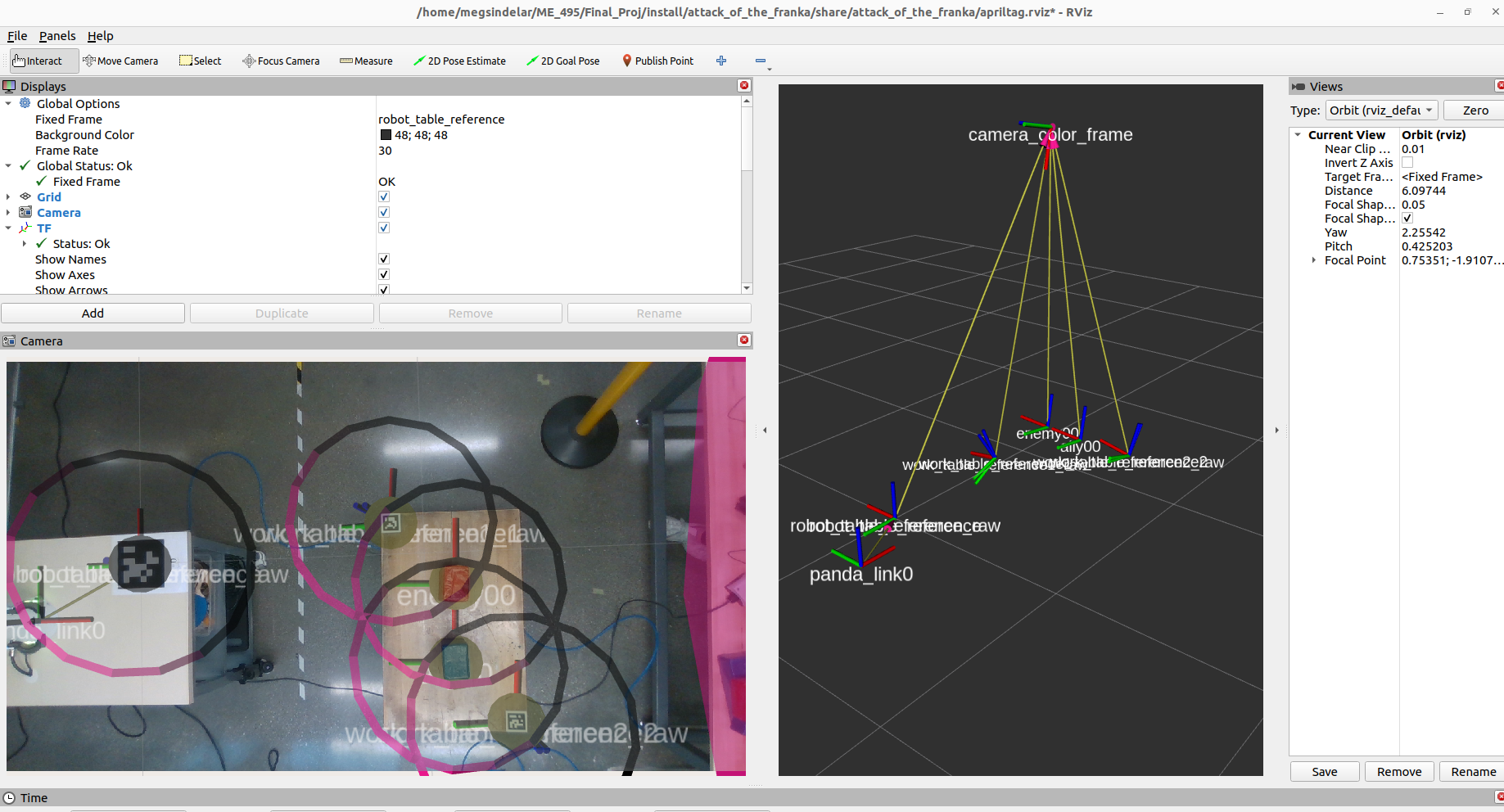
The TF tree and camera feed with overlaid frames, as represented in RVIZ.
The camera_processor node then detects the blocks in the work area by their color, using the HSV color space, contouring, and a few filters to improve detection. The 2D pixel location of the blocks in the image is combined with depth data to determine the 3D relative position of the blocks with respect to the Panda arm.
Expand for more technical details on the block detection system.
The camera_processor node subscribes to the color and aligned depth image data and processes it using OpenCV. The color data is converted into the HSV color space, which helps reduce problems in color detection caused by lighting changes. A certain range of HSV values representing red colors is defined as “enemy” and likewise another blue range defines “allies.”
Pixels that fall into these ranges are grouped by contouring, and each contour is considered a detected object. Opening and closing morphological transformations are applied on the contours to improve their quality. Then, the centroid of each contour is calculated, which is considered the detected object’s position in the camera feed. This pixel position can be combined with the depth data for that pixel and deprojected into 3D real world coordinates of the object in the camera’s reference frame. Knowing the position of the object relative to the camera reference frame means that, since we already know the position of the robot relative to the camera, we can now determine the position of the detected objects relative to the robot.
Finally, a few filters are applied to ensure we only consider detected objects we care about. The position of each object is compared with the work area bounds (as defined by the AprilTags), and any objects outside of the work bounds are filtered out. Also, each object’s depth from the camera is compared to a range from the location of the work table, and objects outside of that range are filtered out. This allows us to ignore enemies that have been knocked over, which we consider “vanquished.”
The 3D real world coordinates of the detected objects are broadcast as transformations, which gives the motion subsystem the information needed to plan out the Panda’s attacks.
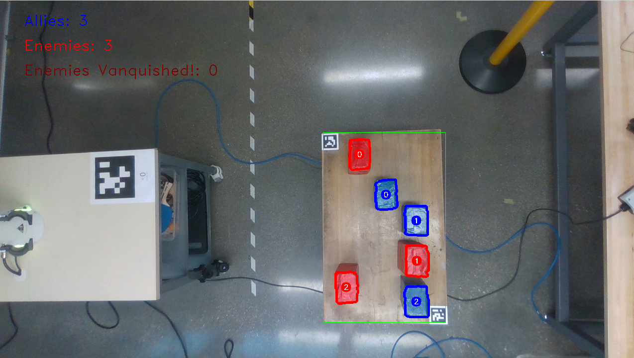
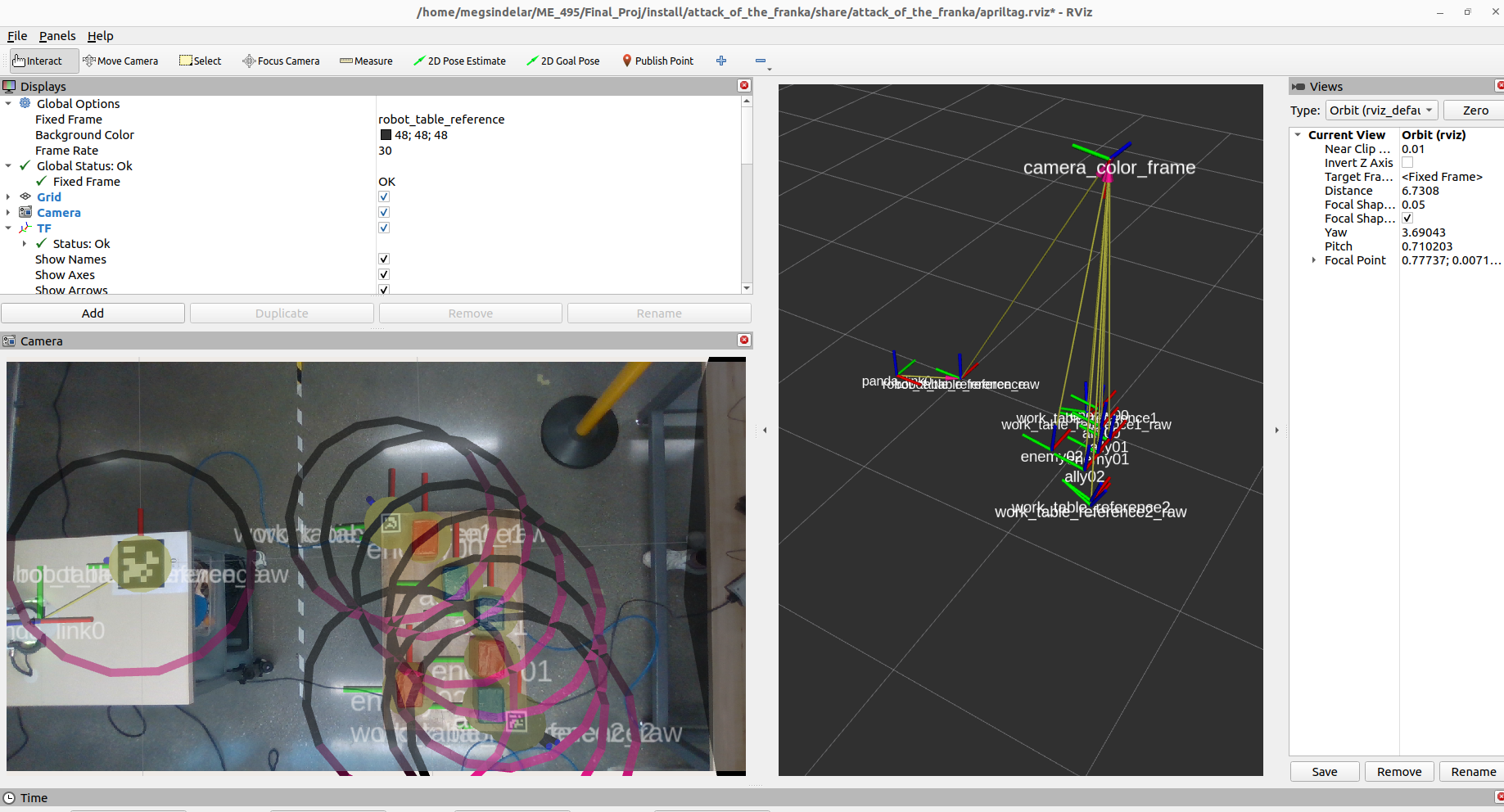
As more objects are detected, the CV node publishes more frames accordingly.
Motion
As of the completion of this project, no Python bindings were available for the MoveIt 2 Motion Planning Framework, which was critical to planning and executing motion for the complicated 7-DoF Panda arm. So in place of an official Python API, we simply made our own basic version.
The API was implemented as a Python class, which is used inside of the Python robot_control node that handles all motion.
Expand for more technical details on the API.
Our API handled:
- Reading and publishing to the
planning sceneto ensure the robot and the lightsaber it wielded did not collide with objects in the environment - Interfacing with the
compute_ikservice to determine joint positions that would move the end-effector to a desired pose - Interfacing with the
move_actionaction to plan a collision-free trajectory to the desired joint positions - Interfacing with the
execute_trajectoryaction to execute previously planned trajectories
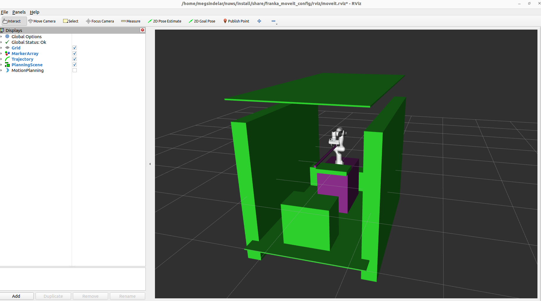
The planning scene represented in RVIZ, with the lightsaber grasped in the Panda’s grippers.
By adding collision objects - like the walls, tables, and ceiling - to the planning scene, the MoveIt framework knows that the robot cannot move into or allow the lightsaber to collide with those objects.
The robot’s first task is to draw its lightsaber from a fixed sheath attached to its table. In order to do this, we plan a trajectory to the fixed starting position of the lightsaber, grasp it, and return to ready position, avoiding collisions along the way.
Expand for more technical details on the collision avoidance.
The lightsaber is added to the planning scene as a special attached collision object - meaning it moves with the robot and is allowed to collide with certain robot links (like the end-effector in which it is grasped). When grasping the lightsaber, it starts as a collision object so the arm will avoid it. Once grasped, the lightsaber changes to an attached collision object so collision-free trajectory plans account for it.
Picking up the lightsaber and a left swipe attack.
From there, the robot has to plan its attacks. The robot_control node relies on the published transformations from the CV system to locate the detected objects. It prioritizes protecting its allies over knocking over enemies, so a single attack style is not sufficient to successfully vanquish most enemies. The Panda instead has an option of three attack styles: a left swipe, a right swipe, and a stab. These attack styles are prioritized in that order.
A right swipe attack.
Once an attack style is selected, the node will plan and execute a trajectory for that attack. If multiple enemies are present in the scene, the robot will attack each one from left to right (from its perspective).
After executing each attack, the camera is checked to see if the attack has been successful. The robot will retry if for some reason it missed or failed to knock over an enemy. If any enemy cannot be attacked due to the configuration of allies in the work area, that enemy is skipped.
A stab attack.
Expand for more technical details on the attack planning.
The process for selecting an attack style has two checks. First, there is a simple geometric check - using the position of the objects from CV - to determine if a selected attack style will cause an enemy to fall into an ally. Secondly, the node attempts to plan motion to attack in that selected attack style. For this check, the allies are added as collision objects in the planning scene. If a collision were to occur during the motion, this plan fails.
If either of these checks fail for a particular attack style, the same checks are attempted on the next attack style. If no attack style would successfully knock down an enemy without affecting an ally, the robot simply does not attack that enemy.
These attacks use several joint state waypoints, adjusted for the position of the enemy, in order to ensure the motion planning reliably completes.
Conclusions
This project was a great opportunity to learn motion control of a real robot through ROS and unify it with computer vision.
We learned several lessons through this project. Environmental factors such as lighting can have a heavy effect on computer vision systems, and the systems must be designed robustly enough to be able to handle different conditions that they might encounter. Furthermore, differences between real hardware and simulation are crucial to understand, especially when it comes to motion. Real life systems do not behave perfectly, and tolerances that can be achieved in simulation may be unattainable in reality. We encountered this especially when commanding fast motions of the arm, which produced larger errors in position than appeared in simulation.
Overall I’m looking forward to more chances to design multi-faceted robotic systems with ROS!
Future Work
1. Improving motion planning robustness.
The most impactful future improvement to this project would be to increase the robustness of the motion planning algorithms. With arbitrary enemy and ally positions, there are many scenarios and edge cases, not all of which the team was able to test. Planning for more of these edge cases and better defining specific motions to handle them would improve the performance of the system. Adding even more possible attack styles could also reduce the number of enemies that are unreachable due to configuration of allies in the work area.
2. Adding more object detection methods.
This project was based on color detection as a central method of detecting and differentiating object types. It would be an exciting challenge to expand this object detection capability. For example, one could use YOLO or other neural networks to analyze the image and detect multiple different types of objects that represent allies and enemies based on a training dataset.
Team Organization
In order to complete this project in the span of just a few weeks, our team assigned roles and areas of focus for development (although each of us contributed to both the Computer Vision and Motion development). The team consisted of:
| Sushma Chandra - Usability Engineer, CV Development | Vaishnavi Dornadula - Usability Engineer, Motion Development |
| Nick Morales - Systems Integrator, CV Development | Meg Sindelar - Reliability Engineer, Motion Development |
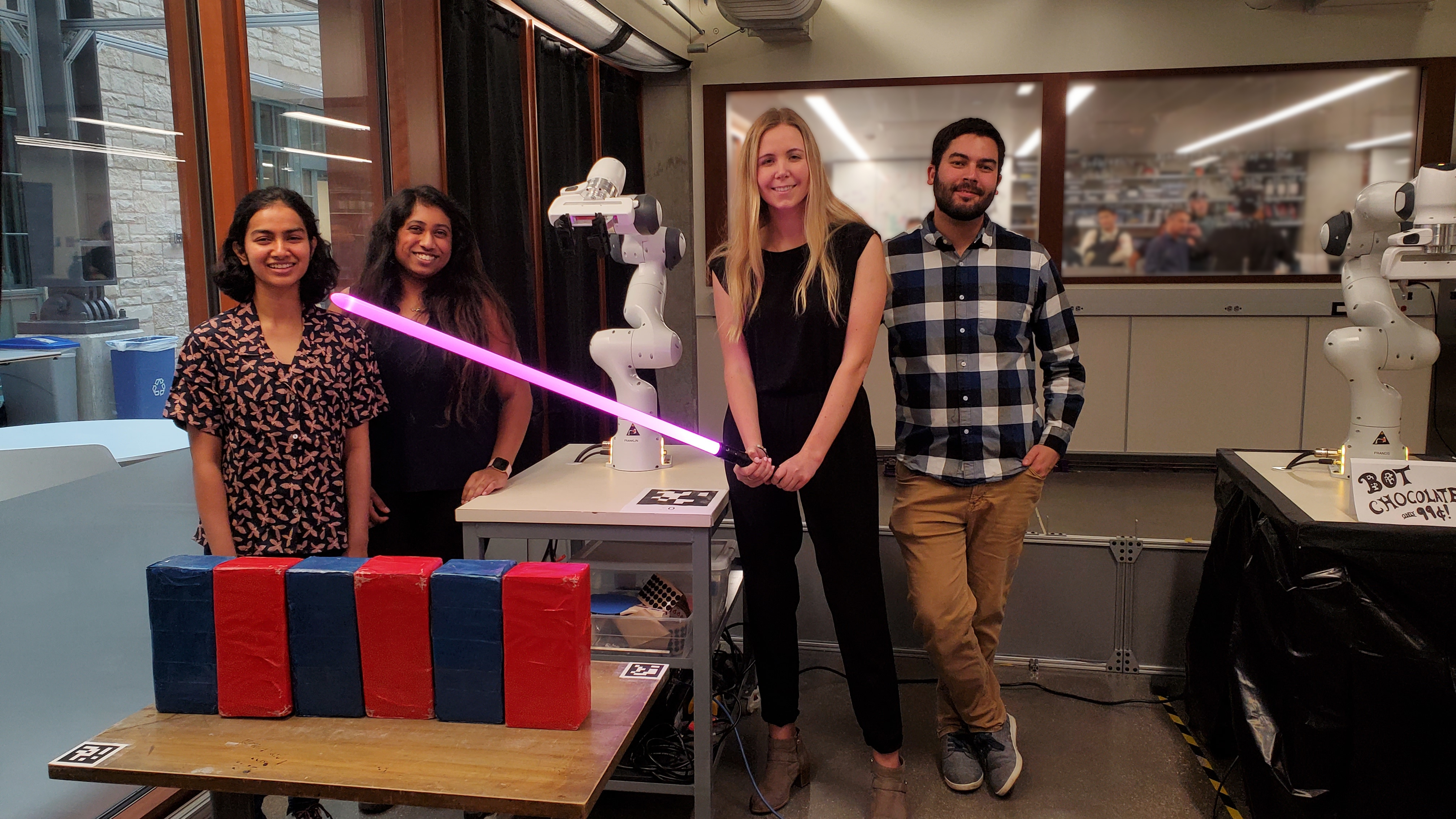
The Attack of the Franka team!
If you’d like to see more videos of the project, here’s a playlist of attack scenarios: